Linux Infrared Control Part 3: Final Hardware
Would you like to use a remote control to control your computer? How about using your computer to send remote control signals to your TV or Stereo instead of using the remote?
Linux Infrared Control Posts
Linux Infrared Control Part 1: Receive IR
Linux Infrared Control Part 2: Send IR
Linux Infrared Control Part 3: Final Hardware
Linux Infrared Control Part 4: Trigger Apps via IR
Introduction
This is the third in a series of posts where I will describe how to use a Raspberry Pi, Raspbian and Linux Infrared Remote Control (Lirc) to receive and send infrared remote control signals. This post will be focused on finalizing the hardware created and depends on Linux Infrared Control Part 1: Receive IR and Linux Infrared Control Part 2: Send IR.
Linux Infrared Remote Control (Lirc) has been around for many years and is an example of a “traditional” unix application: it can do many things and is tricky to setup. With a Raspberry Pi and a few cheap electrical parts it is possible to create a custom remote control or have your computer respond to your existing remote.
The presence of the general purpose input output (GPIO) pins on the Raspberry pi allows the control of external circuits from a linux computer. These instructions will use Linux Infrared Remote Control (Lirc), a well established and tested collection of applications, to receive input and send output.
Approach
Breadboards and jump wires are good for prototyping and temporary solutions, but once the design is finalized, it should be soldered together and in a more permanent way.
My goals for the final lirc hardware was to have the electronics packaged in a neat and clean way and the GPIO connections removable (ie not soldered to the board).
The IR transmitter and receiver are connected to the circuits using polarized connectors. The transmitter used in the final design is commonly known as an IR blaster is widely available online. The IR blaster headphone jack is cut off and replaced with a polarized connector. The IR receiver diode leads are crimped and inserted into a 3 pin polarized housing.
The three sections below describe different electronic packaging options and considerations connecting to the GPIO headers.
Build 1
My first version, build 1, was an attempt in keep everything in the Raspberry Pi case. The circuit was soldered onto a small perfboard and the circuit slightly changed to combine the grounds into one. The whole assembly was bolted to the interior of the Raspberry Pi case so that the headers aligned with an existing cut out. To fit everything in the enclosure the RCA plug was desoldered and removed with pilers. This was a bit of a gamble, but as this was an old device, removing the RCA plug was low risk.
Here is the modified circuit, with the ground combined into one wire.
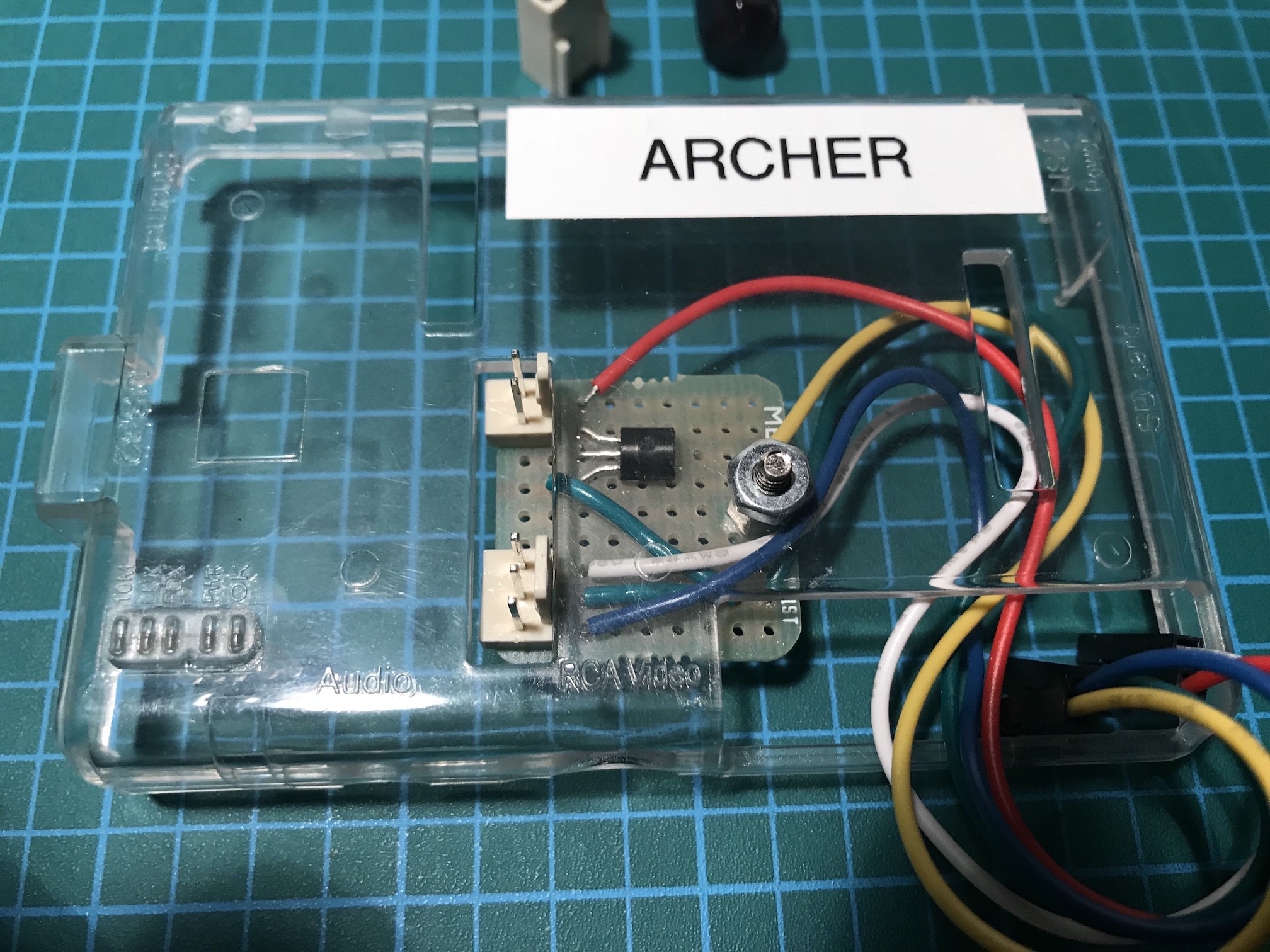
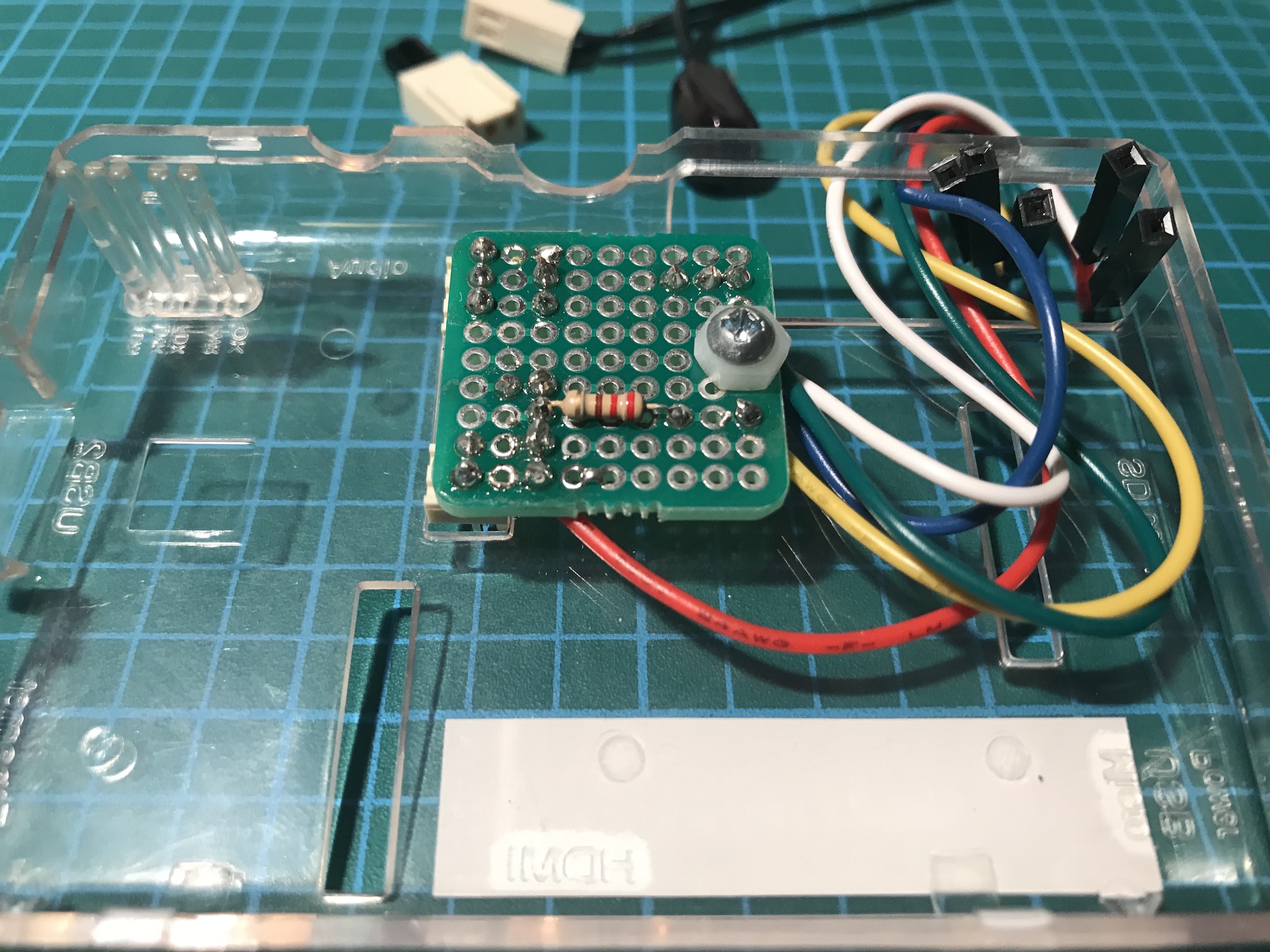
I don’t have any in progress pictures soldering the perf board, but here are two shots of the top of the board and bottom. For space reasons, the resistor was moved to the bottom. The perf board that was used had three pins connected, if you look closely you can see the traces. Please ignore my crap soldering skills.
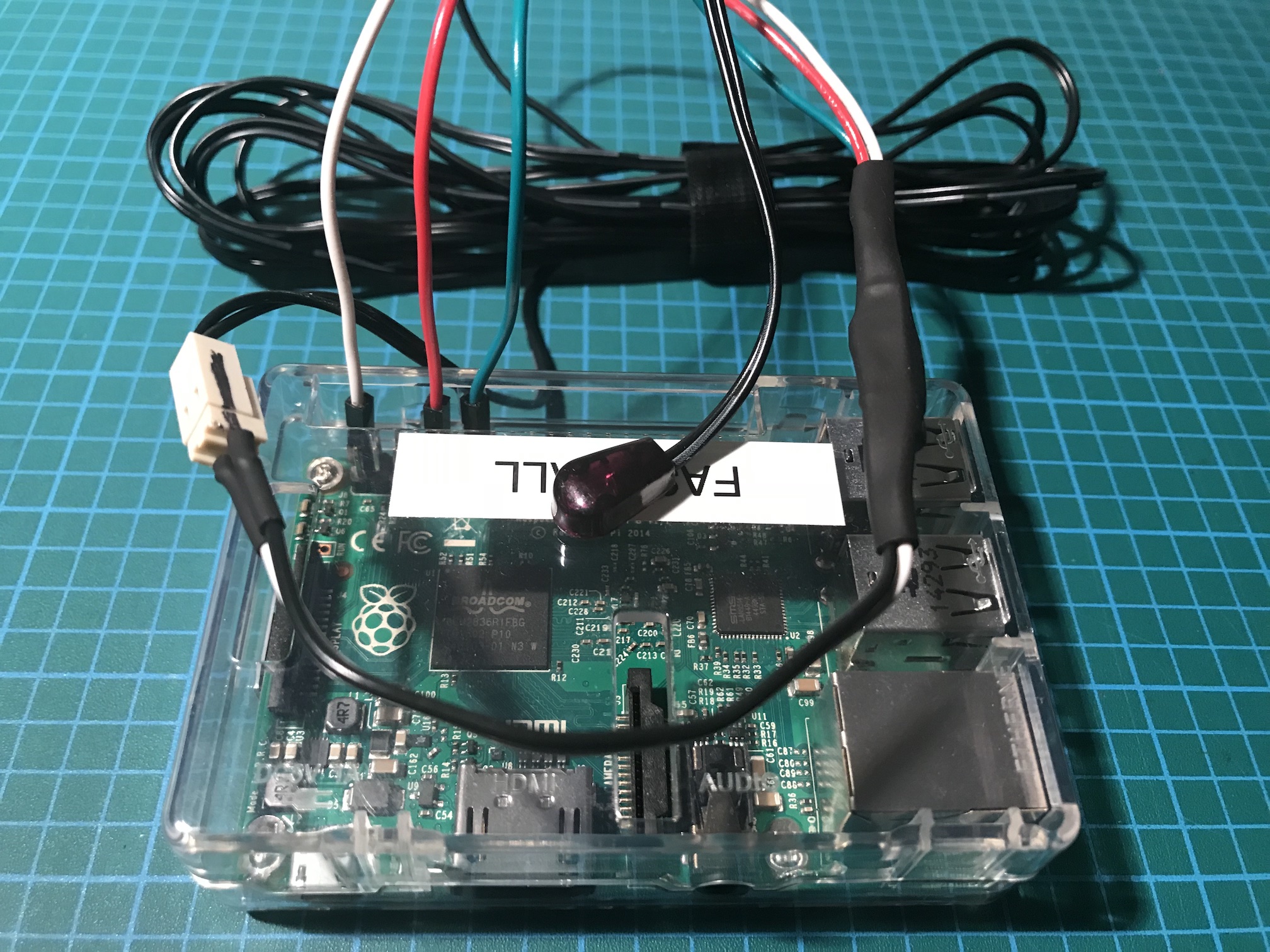
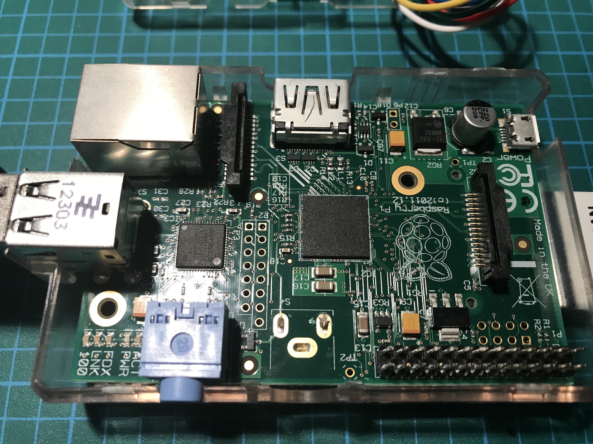
Here is what the Raspberry Pi looks like with the RCA connector removed.
Here is the final assembled device.
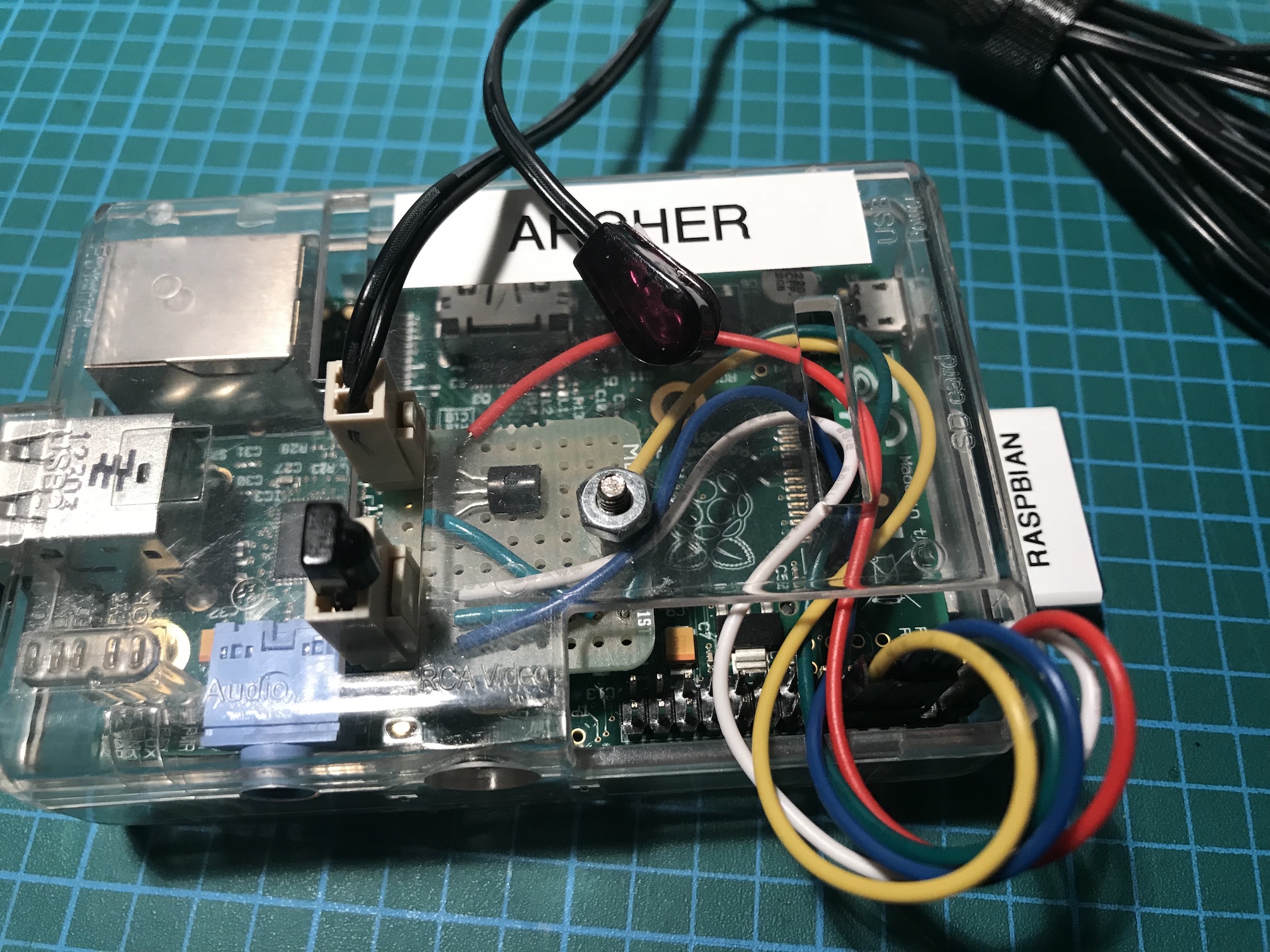
The result was reasonably clean and tidy, two drawbacks are the wires to the GPIO pins are exposed and could get pulled out and that the RCA plug had to be removed.
A new 3d printed case with extra room for the perf board might be the next step for this design.
Build 1 Hardware
Polarized Connector 2 pin
https://www.creatroninc.com/product/2-pin-polarized-connector-set/
https://www.sparkfun.com/products/8095
https://www.sparkfun.com/products/8233
Polarized Connector 3 pin
https://www.creatroninc.com/product/3-pin-polarized-connector-set/
https://www.sparkfun.com/products/8096
https://www.sparkfun.com/products/8232
Polarized Connectors Crimp Pins
https://www.sparkfun.com/products/8100
ProtoBoard – Square 1″ Single Sided
https://www.sparkfun.com/products/8808
https://www.canakit.com/protoboard-square-1-single-sided-prt-08808.html
Misc bolts and spacers from local hardware store
Build 2
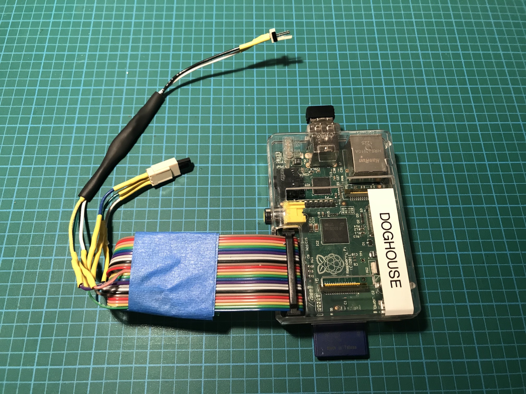
My second version, build 2, used heat shrink tubing to insulate the connections and put everything in the wire. The trade off was that the wire package was stiff and not flexible. This design also separated the receiver from the transmitter.
Here is the modified circuit diagram, without a circuit board.
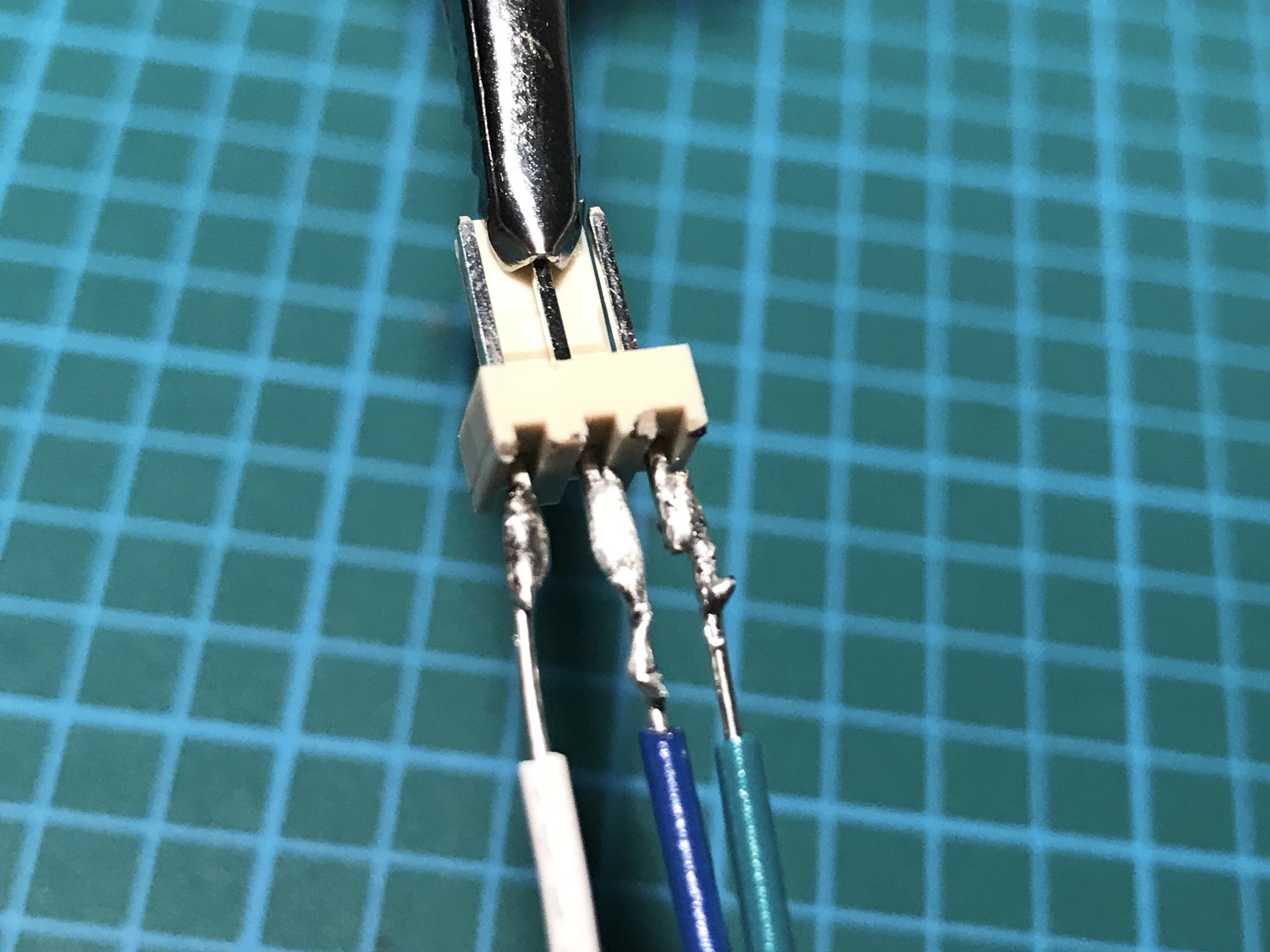
The polarized connector for the IR sensor was soldered right to the wires. The connector leads and wires were lightly tinned then soldered parallel to each other (side by side) and used heat shrink tubing to insulate. Soldering like this is not mechanically strong, but there should not be much stress on the connections. Again my crap soldering skills on display.
The transistor the leads and wires were bent back into a ‘C’, hooked together and crimped shut with pliers before soldering. This provides a stronger mechanical connection then soldering the wires in parallel and is preferable if the leads are long enough.
Then, similar to the polarized connector for the IR sensor, the connections were covered in heat shrink tubing to insulate.
Finally, the components were enclosed in an even larger heat shrink tube to offer more protection and to clean up the package.
The first version of build 2 was connected to the GPIO using dupont connectors, similar to build 1. The second version was soldered to a ribbon cable and although this does work and allows the whole package to be removed from the GPIO, the overall aesthetic is a little messy. More thoughts about this later.
Build 2 Hardware
Polarized Connector 2 pin
https://www.creatroninc.com/product/2-pin-polarized-connector-set/
https://www.sparkfun.com/products/8095
https://www.sparkfun.com/products/8233
Polarized Connector 3 pin
https://www.creatroninc.com/product/3-pin-polarized-connector-set/
https://www.sparkfun.com/products/8096
https://www.sparkfun.com/products/8232
Polarized Connectors Crimp Pins
https://www.sparkfun.com/products/8100
Heat shrink tubing
https://www.creatroninc.com/product/assorted-heat-shrink-kit/
https://www.sparkfun.com/products/9353
https://www.adafruit.com/product/1649
Wire
https://www.creatroninc.com/product/22awg-hookup-wire-assortment-solid/
https://www.sparkfun.com/products/11367
https://www.adafruit.com/product/1311
GPIO Header Connection Options
The only outstanding issue for me was the connections to the GPIO headers. My ideal solution would be to have something removable, but also not something that might be accidentally pulled off.
The typical Raspberry Pi case design has a cutout to expose the GPIO port to allow dupont connectors (the connectors on almost all jump wires) to be easily plugged in. My concern is that this exposure also allows them to be accidentally unplugged too.
One solution is to get a bigger case to include everything inside, only exposing the polarized connectors.
Soldering to a socket plugged into the pins is an option, but the risk there is that the exposed pins from the socket might short out (assuming the socket is taller then the surrounding case).
I did a test with a ribbon cable and connector. I was able to separate the wires and successfully solder them to the build 2 version of the solution. I don’t entirely trust my solder connections from the stranded wire to solid core and aesthetically speaking, the ribbon cable didn’t look as nice as I thought it would.
Although not very common, there are 26 pin crimp sockets that could be used, basically a large set of dupont connectors. In this solution, the individual wires would be crimped and inserted into the correct socket on the connector.
Conclusion
Hopefully with either of these designs you can implement a permanent installation for your IR application and can solder better then I can.