Linux Infrared Control Part 1: Receive IR
Would you like to use a remote control to control your computer? How about using your computer to send remote control signals to your TV or Stereo instead of using the remote?
Linux Infrared Control Posts
Linux Infrared Control Part 1: Receive IR
Linux Infrared Control Part 2: Send IR
Linux Infrared Control Part 3: Final Hardware
Linux Infrared Control Part 4: Trigger Apps via IR
Introduction
This is the first in a series of posts where I will describe how to use a Raspberry Pi, Raspbian and Linux Infrared Remote Control (Lirc) to receive and send infrared remote control signals. This first post will be focused on setup and receiving input.
Linux Infrared Remote Control (Lirc) has been around for many years and is an example of a ‘traditional’ unix application: it can do many things and is tricky to setup (the documentation even says a much). With a Raspberry Pi and a few cheap electrical parts it is possible to create a custom remote control or have your computer respond to your existing remote.
The presence of the general purpose input output (GPIO) pins on the Raspberry pi allows the control of external circuits from a linux computer. These instructions will use Linux Infrared Remote Control (Lirc), a well established and tested collection of applications, to receive input and send output.
Raspberry Pi Models
A quick note about Raspberry Pi models. All Raspberry Pis have a row of GPIO pins, but depending on the model, some of have either 26 or 40 pins. To confuse things a little more, early models changed what some pins did.
In an attempt to keep things simple, these instructions will use the following pins which are the same across all models:
- Pin 8 (GPIO 14) for input
- Pin 1 for input power
- Pin 6 for input ground
- Pin 10 (GPIO 15) for output
- Pin 2 for output power
- Pin 14 for input ground
GPIO Pins
It should be noted there are two ways to refer to the pins. One way is by pin number, starting at 1, labeled on the board with P1. A second way is by pin function, such as GPIO1, TXD0 etc. FYI there are multiple GND, +3V3 and +5V pins. These instructions will be using pin numbers.
Install & Update Raspbian
Rather then re-hash how to install Raspbian on a SD / MicroSD, please see the official instructions. Use Etcher, it makes things much easier and less likely to make your computer unbootable.
Software Versions
Testing was done with 2017-09-07-raspbian-stretch-lite, which included lirc version 0.9.4c.
Different versions of Raspbian or lirc may have different results.
After installing, connect the Raspberry Pi to the internet and login.
First change your password.
passwdOptionally enable ssh, run `raspi-config`:
sudo raspi-configSelect `Interfacing Options`, select `SSH`, Enabled `YES`. Also at this point consider changing your hostname and any localization settings.
Apply all updates:
sudo apt-get update && sudo apt-get upgrade -y
sudo apt-get dist-upgrade -y
sudo apt-get autoremove -y
rpi-update
Previously it was recommended to install and run rpi-update, which updates the firmware and kernel, this is no longer recommended.
As a result of running rpi-update, test and developmental firmware and kernels were installed, which can be unstable and some do not include the lirc drivers. As a result it is no longer recommended to run rpi-update.
Reboot to make sure changes are live:
sudo rebootFinally, install lirc:
sudo apt-get install lirc -yThis installs version 0.9.4c of the lirc package.
Configure Rasbpian and Lirc
Edit `/boot/config.txt` to configure gpio pin 14 (input):
sudo vi /boot/config.txt#dtoverlay=lirc-rpi
# ADDED
dtoverlay=lirc-rpi
dtparam=gpio_in_pin=14Edit `/etc/lirc/lirc_options.conf` to configure to use the Raspberry Pi GPIO pins by changing the `driver` from `devinput` to `default`:
sudo vi /etc/lirc/lirc_options.conf# These are the default options to lircd, if installed as
# /etc/lirc/lirc_options.conf. See the lircd(8) and lircmd(8)
# manpages for info on the different options.
#
# Some tools including mode2 and irw uses values such as
# driver, device, plugindir and loglevel as fallback values
# in not defined elsewhere.
[lircd]
nodaemon = False
# CHANGED
#driver = devinput
driver = default
device = auto
output = /var/run/lirc/lircd
pidfile = /var/run/lirc/lircd.pid
plugindir = /usr/lib/arm-linux-gnueabihf/lirc/plugins
permission = 666
allow-simulate = No
repeat-max = 600
#effective-user =
#listen = [address:]port
#connect = host[:port]
#loglevel = 6
#uinput = ...
#release = ...
#logfile = ...
[lircmd]
uinput = False
nodaemon = False
# [modinit]
# code = /usr/sbin/modprobe lirc_serial
# code1 = /usr/bin/setfacl -m g:lirc:rw /dev/uinput
# code2 = ...
# [lircd-uinput]
# release-timeout = 200Reboot to make the changes live:
sudo rebootReceiver Hardware
Note
Shutdown the Raspberry Pi whenever connections are made to the GPIO pins.
First buy a breadboard, leads and infrared receiver. The receivers are cheap, around $2.00.
This hardware will be to prototype the circuit and will not require soldering.
Breadboard
https://www.creatroninc.com/product/mini-breadboard-white/
https://www.sparkfun.com/products/12043
https://www.adafruit.com/product/65
Male to Female jumper wire
https://www.creatroninc.com/product/6-m-f-jumper-wire-10-pack/
https://www.sparkfun.com/products/9140
https://www.adafruit.com/product/1954
TSOP38238 infrared receiver
https://www.creatroninc.com/product/tsop38238-infrared-receiver-38khz/
https://www.sparkfun.com/products/10266
https://www.adafruit.com/product/157
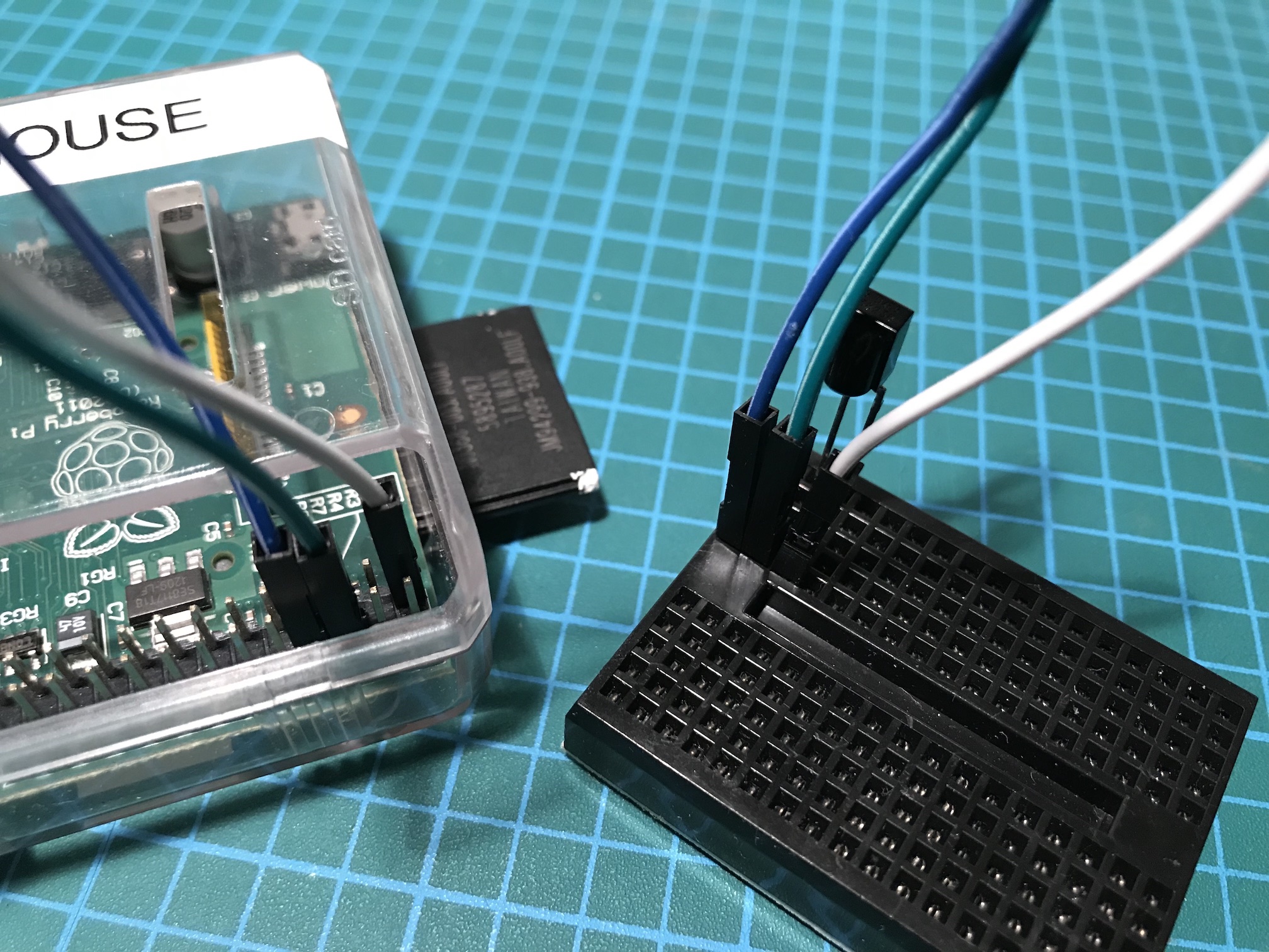
Setup the sensor on the breadboard. There are three leads, if you are using the TSOP38238, lens (‘bump’ on sensor) facing up and should be connected as follows:
+-----------------------+ A
|                       +-----------o +3.3V, Pin 1
|                       |
|      ______________   |
|     /                 |
|    (                  | B
|     \______________ + +-----------o GND, Pin 6
|                       |
|                       | C
|                     - +-----------o GPIO 14, Pin 8
+-----------------------+


              Pin 1 Pin2
           +3V3 [A] [ ] +5V
 SDA1 / GPIO  2 [ ] [ ] +5V
 SCL1 / GPIO  3 [ ] [B] GND
        GPIO  4 [ ] [C] GPIO 14 / TXD0
            GND [ ] [ ] GPIO 15 / RXD0
        GPIO 17 [ ] [ ] GPIO 18
        GPIO 27 [ ] [ ] GND
        GPIO 22 [ ] [ ] GPIO 23
           +3V3 [ ] [ ] GPIO 24
 MOSI / GPIO 10 [ ] [ ] GND
 MISO / GPIO  9 [ ] [ ] GPIO 25
 SCLK / GPIO 11 [ ] [ ] GPIO  8 / CE0#
            GND [ ] [ ] GPIO  7 / CE1#
             Pin 25 Pin 26
Original ASCII art from:
http://aron.ws/projects/lirc_rpi/
http://weyprecht.de/2015/11/30/raspberry-pi-ascii-art/
The wiring should look like:

Receiver Software: Testing with mode2
Now that the circuit is complete, next step is to test the reception of remote control button presses
First stop lirc, if running:
sudo systemctl stop lircd.socket
sudo systemctl stop lircd.service
Second, start `mode2`, which will listen for pulses from the sensor.
mode2 -d /dev/lirc0On start you should see:
Using driver default on device /dev/lirc0
Trying device: /dev/lirc0
Using device: /dev/lirc0
Point remote at receiver, begin pressing buttons. If you see a series of lines like the following, then the circuit is working:
space 10607416
pulse 4503
space 4442
pulse 564
space 1662
pulse 561
space 1657
Press control c to exit mode2.
Reference:
http://www.lirc.org/html/mode2.html
Receiver Software: Capture with irrecord
Next we will create a lirc configuration file for your remote.
As a result of the large number of different remotes with buttons, lirc defines a standard set of button names (commonly referred to as a namespace), the current namespace has over 500 button names. A typical remote will only have a small subset of these names.
To see the list of standard button names, type:
irrecord --list-namespaceBased on the remote being captured, it is worth taking a few minutes and plan out which buttons names should be used.
Existing Remote Configurations
The lirc project does ship with some remote configurations already captured, see `/usr/share/lirc/configs`
Once captured, these button presses can be used to either send out the same button presses using an ir transmitter (sometimes referred to as a irblaster) or listen and execute programs when the button presses are received.
As a demo, we are going to capture the power button on the remote, this is the KEY_POWER in the name space. In part 2, this button press will be transmitted to demo `irsend`.
First stop lirc, if running:
sudo systemctl stop lircd.socket
sudo systemctl stop lircd.service
Second, start `irrecord` and specify an appropriate conf filename:
irrecord -d /dev/lirc0On start the example output look like:
Using driver default on device /dev/lirc0

irrecord -  application for recording IR-codes for usage with lirc
Copyright (C) 1998,1999 Christoph Bartelmus(lirc@bartelmus.de)

This program will record the signals from your remote control
and create a config file for lircd.

A proper config file for lircd is maybe the most vital part of this
package, so you should invest some time to create a working config
file. Although I put a good deal of effort in this program it is often
not possible to automatically recognize all features of a remote
control. Often short-comings of the receiver hardware make it nearly
impossible. If you have problems to create a config file READ THE
DOCUMENTATION at https://sf.net/p/lirc-remotes/wiki

If there already is a remote control of the same brand available at
http://sf.net/p/lirc-remotes you might want to try using such a
remote as a template. The config files already contains all
parameters of the protocol used by remotes of a certain brand and
knowing these parameters makes the job of this program much
easier. There are also template files for the most common protocols
available. Templates can be downloaded using irdb-get(1). You use a
template file by providing the path of the file as a command line
parameter.

Please take the time to finish the file as described in
https://sourceforge.net/p/lirc-remotes/wiki/Checklist/ an send it
to  <lirc@bartelmus.de> so it can be made available to others.

Press RETURN to continue.

Checking for ambient light  creating too much disturbances.
Please don't press any buttons, just wait a few seconds...

No significant noise (received 0 bytes)

Enter name of remote (only ascii, no spaces) :example
Using example.lircd.conf as output filename

Now start pressing buttons on your remote control.

It is very important that you press many different buttons randomly
and hold them down for approximately one second. Each button should
generate at least one dot but never more than ten dots of output.
Don't stop pressing buttons until two lines of dots (2x80) have
been generated.

Press RETURN now to start recording.
................................................................................
Got gap (46527 us)}

Please keep on pressing buttons like described above.
...............................................................................

Please enter the name for the next button (press  to finish recording)
KEY_POWER

Now hold down button "KEY_POWER".

Please enter the name for the next button (press  to finish recording)

Checking for toggle bit mask.
Please press an arbitrary button repeatedly as fast as possible.
Make sure you keep pressing the SAME button and that you DON'T HOLD
the button down!.
If you can't see any dots appear, wait a bit between button presses.

Press RETURN to continue.
..............................Cannot find any toggle mask.

Successfully written config file example.lircd.conf
</lirc@bartelmus.de>
Reference:
http://www.lirc.org/html/irrecord.html
Conclusion
And that is it! Hopefully you have a really simple circuit that is capturing the IR signals from your remote. Next we will transmit this button press back to power on or off the device the remote controlled.