Linux Infrared Control Part 2: Send IR
Would you like to use a remote control to control your computer? How about using your computer to send remote control signals to your TV or Stereo instead of using the remote?
Linux Infrared Control Posts
Linux Infrared Control Part 1: Receive IR
Linux Infrared Control Part 2: Send IR
Linux Infrared Control Part 3: Final Hardware
Linux Infrared Control Part 4: Trigger Apps via IR
Introduction
This is the second in a series of posts where I will describe how to use a Raspberry Pi, Raspbian and Linux Infrared Remote Control (Lirc) to receive and send infrared remote control signals. This post will be focused on sending output and depends on Linux Infrared Control Part 1: Receive IR.
Linux Infrared Remote Control (Lirc) has been around for many years and is an example of a “traditional” unix application: it can do many things and is tricky to setup. With a Raspberry Pi and a few cheap electrical parts it is possible to create a custom remote control or have your computer respond to your existing remote.
The presence of the general purpose input output (GPIO) pins on the Raspberry pi allows the control of external circuits from a linux computer. These instructions will use Linux Infrared Remote Control (Lirc), a well established and tested collection of applications, to receive input and send output.
Configure Rasbpian and Lirc
Edit `/boot/config.txt` to add gpio pin 15 (output), this is in addition to the existing configuration for pin 14 (input) from part 1. The complete edit should look like:
sudo vi /boot/config.txt#dtoverlay=lirc-rpi
# ADDED
dtoverlay=lirc-rpi
dtparam=gpio_in_pin=14
dtparam=gpio_out_pin=15Reboot to make the changes live:
sudo rebootSender Hardware
Note
Shutdown the Raspberry Pi whenever connections are made to the GPIO pins.
In addition to the breadboard and Male to Female jumper wires from part one (you will need 3 more wires for this circuit), you will also need:
IR transmitter LTV-4208 infrared emitter – 940NM
https://www.creatroninc.com/product/ltv-4208-infrared-emitter-940nm/
https://www.sparkfun.com/products/241
https://www.adafruit.com/product/387
220 ohm Resistor (Red, Red, Brown, Gold stripes)
https://www.creatroninc.com/product/14w-assorted-resistor-kit/
https://www.sparkfun.com/products/10969
https://www.adafruit.com/product/2780
BC547 transistor
https://www.creatroninc.com/product/bc547-npn-bjt-50v-01a
https://www.sparkfun.com/products/8928
Data sheet for BC547 transistor
https://www.sparkfun.com/datasheets/Components/BC546.pdf
Note
If you get a different transistor, check the data sheet for the transistor to make sure it is wired correctly, otherwise you can fry your components and let out the magic smoke.
Our control input flows into the base, the output is tied to the collector and the emitter is kept at a fixed voltage.
Setup the circuit on the breadboard. There are three leads to the BC547 transistor, with the flat side facing up, and should be connected as follows:
+-------------------+
|                   +---------------------o Emitter, IR LED
|                   |
|                   |
|     Flat Side     + --------------------o Base, 220 ohm Resistor
|                   |
|                   |
|                   +---------------------o Collector, Pin 14 (GND)
+-------------------+
The complete circuit diagram looks like:
     Pin 2 A o----------------------------+
     (+5V)                                |   (longer lead towards pin 2)
                                         _|_
                                         \ /  --> LTE-4208
                                         ---  --> IR LED
                                          |
                                BC547     |
                   ___                +---+  [Emitter]
    Pin 10 B o----|___|---------------|
    (GPIO15)     220 ohm       [Base] +->-+  [Collector]
                                          |
                                          |
    Pin 14 C o----------------------------+
    (GND)
IR LED short leg is cathode (-), towards BC547 transistor
              Pin 1 Pin2
           +3V3 [ ] [A] +5V
 SDA1 / GPIO  2 [ ] [ ] +5V
 SCL1 / GPIO  3 [ ] [ ] GND
        GPIO  4 [ ] [ ] GPIO 14 / TXD0
            GND [ ] [B] GPIO 15 / RXD0
        GPIO 17 [ ] [ ] GPIO 18
        GPIO 27 [ ] [C] GND
        GPIO 22 [ ] [ ] GPIO 23
           +3V3 [ ] [ ] GPIO 24
 MOSI / GPIO 10 [ ] [ ] GND
 MISO / GPIO  9 [ ] [ ] GPIO 25
 SCLK / GPIO 11 [ ] [ ] GPIO  8 / CE0#
            GND [ ] [ ] GPIO  7 / CE1#
             Pin 25 Pin 26
Original ASCII art from:
http://aron.ws/projects/lirc_rpi/
http://weyprecht.de/2015/11/30/raspberry-pi-ascii-art/
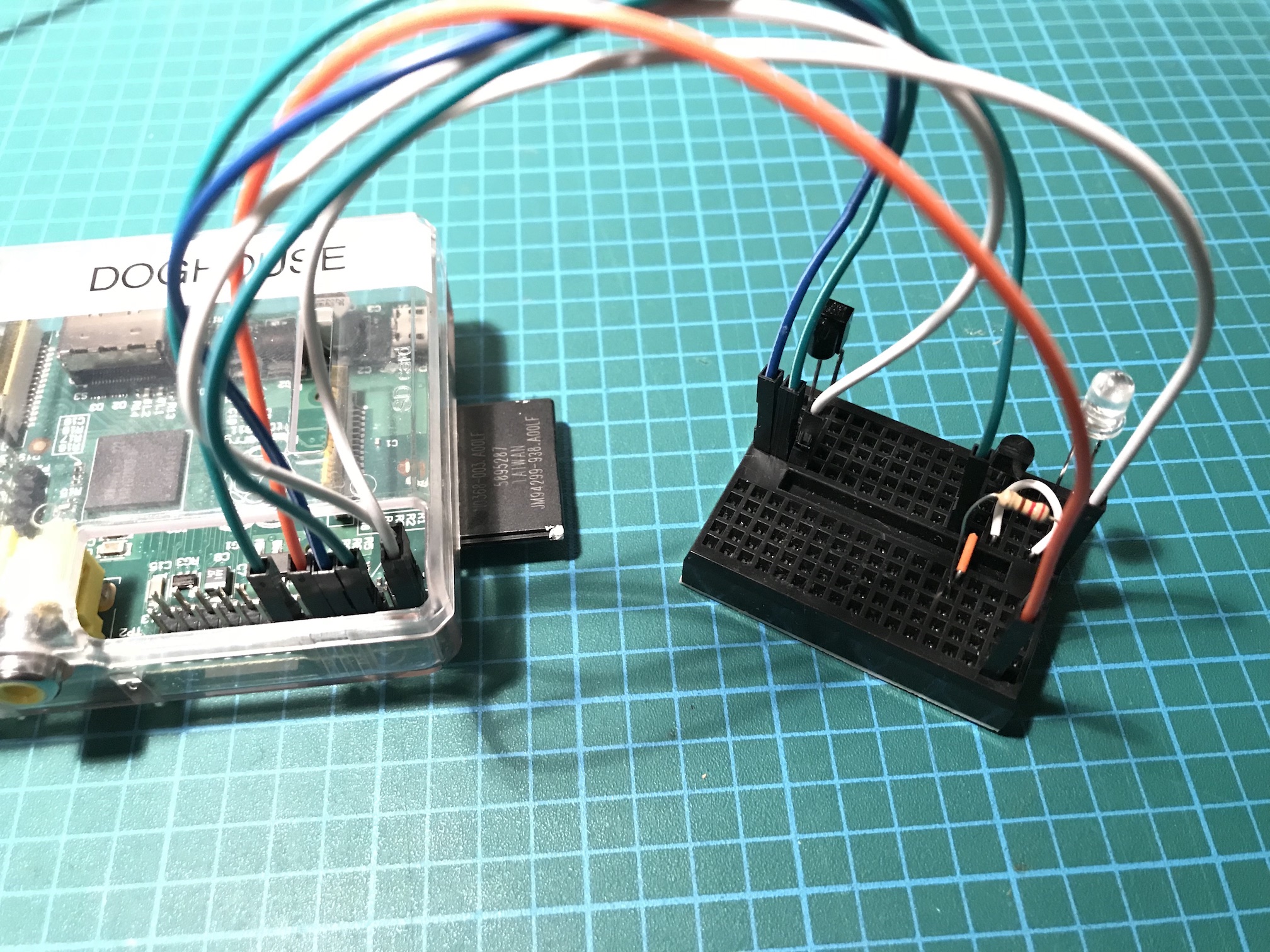
The wiring should look like:
Configuration For Remote Buttons
The example configuration file `example.lircd.conf` created in part 1 will be used to test the sender hardware. Copy the config file to `/etc/lirc/lircd.conf.d/`:
sudo cp ~/example.lircd.conf /etc/lirc/lircd.conf.d/The configuration should look something like this:
sudo vi /etc/lirc/lircd.conf.d/example.lircd.conf#
# this config file was automatically generated
# using lirc-0.8.4a(default) on Wed Jul 29 02:33:44 2009
#
# contributed by
#
# brand: Example
# model no. of remote control:
# devices being controlled by this remote:
#
begin remote
name example
bits 16
flags SPACE_ENC
eps 30
aeps 100
header 4501 4446
one 569 1663
zero 569 545
ptrail 561
pre_data_bits 16
pre_data 0xE0E0
gap 46925
toggle_bit_mask 0x0
begin codes
KEY_POWER 0x40BF # Was: Power
end codes
end remoteRestart `lircd.service` to load the configuration:
sudo systemctl stop lircd.service
sudo systemctl start lircd.service
Test Transmitter Hardware
This test will use a the example remote configuration by sending the only configured button, the `KEY_POWER` button. Move the circuit near the device that the remote from step 1 controlled and see if the device is powered on and off.
Alternately, most camera phones can observe IR light and can be used to view the IR led flashing.
Type the following:
irsend SEND_ONCE example KEY_POWERIf the result is nothing on the command line and device powers on or off, success!
If the result is:
irsend: command failed: SEND_ONCE example KEY_POWER
irsend: transmission failed
Check the status to see if there are any error messages:
sudo systemctl status lircd.service— lirc.service - LSB: Starts LIRC daemon.
Loaded: loaded (/etc/init.d/lirc)
Active: active (running) since Sun 2017-02-05 02:59:55 UTC; 4min 50s ago
Process: 924 ExecStop=/etc/init.d/lirc stop (code=exited, status=0/SUCCESS)
Process: 967 ExecStart=/etc/init.d/lirc start (code=exited, status=0/SUCCESS)
CGroup: /system.slice/lirc.service
└─976 /usr/sbin/lircd --driver=default --device=/dev/lirc0 --uinput
Feb 05 03:01:50 raspberrypi lircd-0.9.0-pre1[976]: accepted new client on /var/run/lirc/lircd
Feb 05 03:01:50 raspberrypi lircd-0.9.0-pre1[976]: removed client
Feb 05 03:01:53 raspberrypi lircd-0.9.0-pre1[976]: accepted new client on /var/run/lirc/lircd
Feb 05 03:01:53 raspberrypi lircd-0.9.0-pre1[976]: removed client
Feb 05 03:02:01 raspberrypi lircd-0.9.0-pre1[976]: accepted new client on /var/run/lirc/lircd
Feb 05 03:02:01 raspberrypi lircd-0.9.0-pre1[976]: removed client
Feb 05 03:04:23 raspberrypi lircd-0.9.0-pre1[976]: accepted new client on /var/run/lirc/lircd
Feb 05 03:04:23 raspberrypi lircd-0.9.0-pre1[976]: removed client
Feb 05 03:04:39 raspberrypi lircd-0.9.0-pre1[976]: accepted new client on /var/run/lirc/lircd
Feb 05 03:04:40 raspberrypi lircd-0.9.0-pre1[976]: removed clientConclusion
If you want back and capture more or all of the buttons for the remote, you can completely control the device from the Raspberry Pi.
In the next post, we will show finalized hardware design options, where the prototyped breadboard circuits are soldered together for more permanent solutions.