Raspberry Pi IR Transmitter
How to configure a Raspberry Pi to transmit IR output using the new kernel drivers, ir-keytable & ir-ctl, rather then LIRC. Building on the previous post, Raspberry Pi IR Receiver.
Introduction
I have been using IR with Raspberry Pis for a few years, using remotes to trigger screen refreshes, change browser tabs and to reboot. Additionally, I have captured IR remote button presses and used them to programatically control devices, instead of using the original remote. The tool for this in the past has been LIRC.
However, recent releases of the linux kernel have removed LIRC support in favour for the new kernel IR drivers.
The following describes how to use the new kernel IR drivers, ir-keytable and ir-ctl to reproduce the functionality previously provided by LIRC.
This is a part of a two article series:
Raspberry Pi IR Receiver
Raspberry Pi IR Transmitter
Approach and Assumptions
Assumes using 2020-02-13-raspbian-buster or 2020-02-13-raspbian-buster-lite.
Raspberry Pi OS
Raspbian was rebranded to Raspberry Pi OS in spring 2020.
The following has been tested and works with 2020-05-27-raspios-buster-lite-armhf.zip.
It is assumed that the Raspberry Pi has been setup following the steps in Raspberry Pi IR Receiver:
Raspberry Pi IR Receiver
Many of the steps are documented as part of ControlKit. ControlKit is collection of notes to setup and control a linux based computer, primarily targeting a Raspberry Pi running Raspbian. Where appropriate, references back to ControlKit notes will be made. This document may go out of date, but ControlKit notes should be current.
To see the ControlKit notes, please see the GitHub repo:
GitHub ControlKit repo
Hardware – Transmitter Wiring Diagram
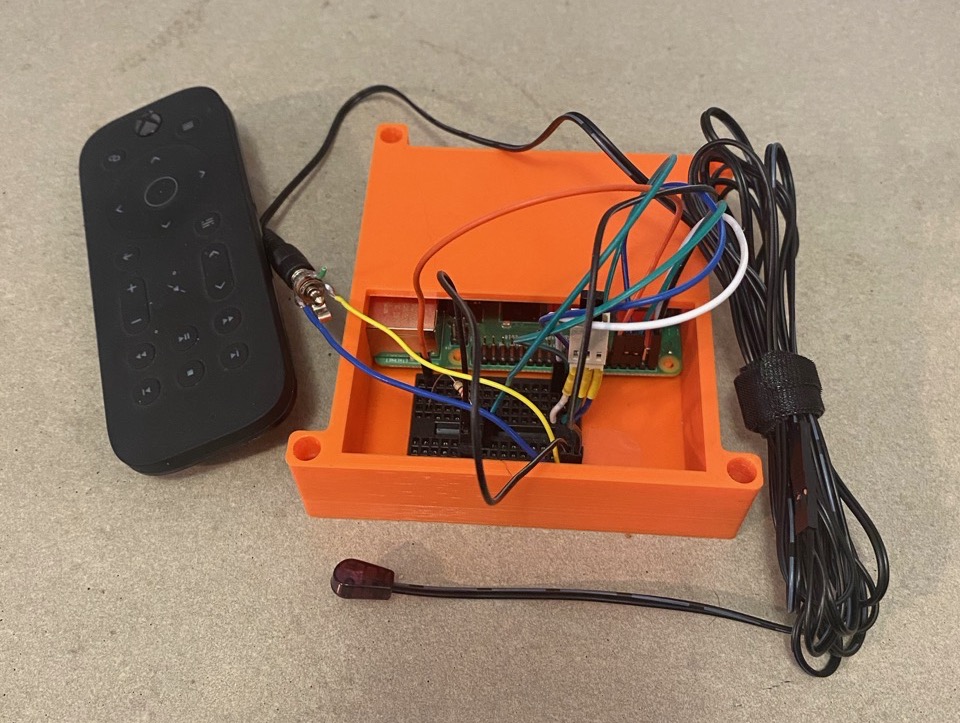
Similarly to the receiver, the hardware required for transmitting IR input is reasonably simple. The recommendation is to prototype the circuit and then permanently solder it when everything has been tested.
In addition to the Raspberry Pi, a 220 ohm resistor, BC547 transistor, IR LED, prototyping bread board and jumper wires are needed.
220 ohm resistor:
https://www.creatroninc.com/product/1-4w-assorted-resistor-kit/
https://www.sparkfun.com/products/10969
https://www.adafruit.com/product/2780
BC547 transistor:
https://www.creatroninc.com/product/bc547-npn-bjt-50v-0-1a/
https://www.onsemi.com/download/data-sheet/pdf/bc550-d.pdf
NOTE: The alternate transistors should work based on the data sheets, but have not been tested.
Alternate transistors, BC337 or PN2222:
https://www.sparkfun.com/products/13689
https://www.adafruit.com/product/756
940nm IR LED:
https://www.creatroninc.com/product/lte-4208-infrared-emitter-940nm/
https://www.adafruit.com/product/387
NOTE: There are 950nm IR LEDs and they should work, but have not been tested.
Breadboard:
https://www.creatroninc.com/product/mini-breadboard-white/
https://www.sparkfun.com/products/12043
https://www.adafruit.com/product/65
Jumper wires:
https://www.creatroninc.com/product/6-m-f-jumper-wire-10-pack/
https://www.sparkfun.com/products/9140
https://www.adafruit.com/product/826
Once successfully prototyped, it is strongly suggested to use a pre-made IR transmitter (often sold as IR Blasters) and a mono jack.
Pre-made IR Blaster:
https://www.amazon.ca/Infrared-Emitter-Extender-Extension-Transmitter/dp/B01H5A3IWY/ref=pd_bxgy_img_3/140-8239435-3587563
Mono Jack:
https://www.creatroninc.com/product/35mm-mono-jack-panel-mount/
https://www.amazon.com/dp/B0002KR42U/
The wiring diagram is as follows:
A) Black wire, Pin 2, +5V, output power
B) Orange wire, Pin 10, GPIO 15, control signal
C) Green wire, Pin 14, GND, ground
              Pin 1 Pin2
           +3V3 [ ] [A] +5V
 SDA1 / GPIO  2 [ ] [ ] +5V
 SCL1 / GPIO  3 [ ] [ ] GND
        GPIO  4 [ ] [ ] GPIO 14 / TXD0
            GND [ ] [B] GPIO 15 / RXD0
        GPIO 17 [ ] [ ] GPIO 18
        GPIO 27 [ ] [C] GND
        GPIO 22 [ ] [ ] GPIO 23
           +3V3 [ ] [ ] GPIO 24
 MOSI / GPIO 10 [ ] [ ] GND
 MISO / GPIO  9 [ ] [ ] GPIO 25
 SCLK / GPIO 11 [ ] [ ] GPIO  8 / CE0#
            GND [ ] [ ] GPIO  7 / CE1#
             Pin 25 Pin 26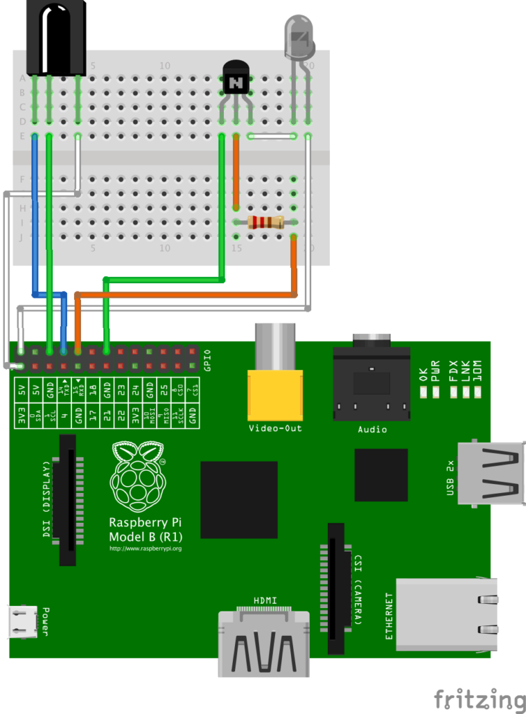
The longer wire on the LED component is the anode and should be on the side of pin 2.
     Pin 2 A o----------------------------+
     (+5V)                                |   (longer lead to pin 2)
                                         _|_
                                         \ /  --> LTE-4208
                                         ---  --> IR LED
                                          |
                                BC547     |
                   ___                +---+  [Emitter]
    Pin 10 B o----|___|---------------|
    (GPIO15)     220 ohm       [Base] +->-+  [Collector]
                                          |
                                          |
    Pin 14 C o----------------------------+
    (GND)
For ControlKit IR hardware notes, please see:
Raspbian GPIO IR Hardware
Raspbian GPIO IR Hardware image
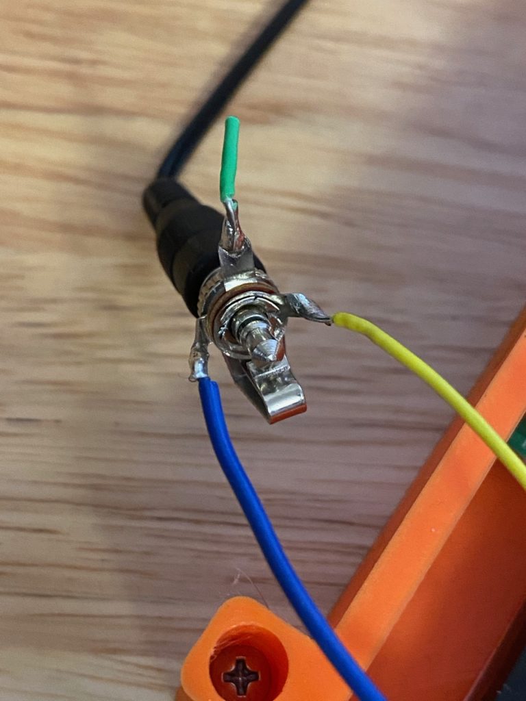
Hardware – Mono Jack
The Mono Jack that was purchased had a somewhat confusing solder points. I suspect it is a stereo jack incorrectly sold as a mono jack. Either way here is how to connect it.
Update
I was informed that third wire for the jack is the alternate path for audio.
When the phone plug is not in the jack, the input audio is routed to the (green) wire, which would normally be a built in speaker.
When the phone plug is inserted into the jack, the plug forces the contacts apart disconnecting the speaker, and thus muting the sound.
The following describes the orientation and soldering connections made.
Orientation female connection pointing away, flat centre contact at bottom
Left solder point is the centre contact, connected to the Raspberry Pi GPIO
Right solder point is outer contact, connected to the transistor in the circuit
Center top solder point is not used
Configure Raspbian
Once the circuit is setup and connected to the Raspberry Pi, Raspbian needs to be configured to use the circuit.
Please review the Configure Raspbian section from Raspberry Pi Receiver and be sure to include dtoverlay=gpio-ir-tx,gpio_pin=15 when configuring config.txt.
The following is taken from ControlKit Raspbian Setup and Configure IR:
Raspbian Setup and Configure IR
How to Transmit Remote Power Button Press to Turn on TV
First, determine the keycode from the keymap file.
This example will show how to send the KEY_SLEEP scancode for the MCE remote rc-6.
Find the scan code by searching for ‘SLEEP’ in the toml configuration file for the rc6 remote:
cat /etc/rc_keymaps/rc6_mce.toml | grep SLEEPThe output should be:
0x800f040c = "KEY_SLEEP"To transmit, use the rc6_mce protocol and 0x800f040c scancode:
ir-ctl -S rc6_mce:0x800f040c -d /dev/lirc1Although the device /dev/lirc1 is used, lirc is not installed.
This should transmit the KEY_SLEEP IR button press, any device that uses the rc6 protocol should sleep or power off.
Transmit Remote Key Presses for Remotes with Unsupported Protocols
There are some remote IR protocols are not supported by the kernel. For those remotes, it is possible to capture and transmit the raw signal.
For each button press, redirect the input to a file.
This example will show how to capture the power button by redirecting the raw signal to JVC-RM-AJ777-KEY_POWER.txt:
ir-ctl -d /dev/lirc1 -r > ./JVC-RM-AJ777-KEY_POWER.txtTo transmit the captured codes, run ir-ctl using the JVC-RM-AJ777-KEY_POWER.txt file as input:
ir-ctl -d /dev/lirc0 --send=./JVC-RM-AJ777-KEY_POWER.txtWhen capturing a button press, it is possible to capture more than one button press unintentionally. During transmission of the captured IR codes, the behaviour of the device may reveal the multiple capture.
Alternately, by manually inspecting the file it might be possible to see multiple captures based on repeating patterns and length.
How to Receive Button Press and Transmit Different Button Press
Briefly, configure triggerhappy to call ir-ctl, which then uses either supported or unsupported IR remote protocols to transmit a button press. In this way it is possible to map one remote to a different one.
How to Transmit Buttons to Navigate TV UI and Macros
Similarly, configure triggerhappy to call a script which includes more than one ir-ctl and where required, sleep statements to allow for delays pauses. This can provide a macro to navigate a TV UI for example.
Summary
Once the hardware and configuration is done, the tweaking and customization can begin. It is almost magical to use a remote to control a computer, rebooting it or scripting TVs to switch modes with one button press.