Raspberry Pi IR Receiver
How to configure a Raspberry Pi to receive IR input from a remote control using the new kernel drivers, ir-keytable & ir-ctl, rather then LIRC. Then using that input to run a script to reboot the device.
Introduction
I have been using IR with Raspberry Pis for a few years, using remotes to trigger screen refreshes, change browser tabs and to reboot. Additionally, I have captured IR remote button presses and used them to programatically control devices, instead of using the original remote. The tool for this in the past has been LIRC.
However, recent releases of the linux kernel have removed LIRC support in favour for the new kernel IR drivers.
The following describes how to use the new kernel IR drivers, ir-keytable and ir-ctl to reproduce the functionality previously provided by LIRC.
This is a part of a two article series:
Raspberry Pi IR Receiver
Raspberry Pi IR Transmitter
Approach and Assumptions
Assumes using 2020-02-13-raspbian-buster or 2020-02-13-raspbian-buster-lite.
Raspberry Pi OS
Raspbian was rebranded to Raspberry Pi OS in spring 2020.
The following has been tested and works with 2020-05-27-raspios-buster-lite-armhf.zip.
Assumes a reasonable level of familiarity with Linux and the command line. Should be able to edit text files in vi without issue.
Assumes an IR remote that supports rc-5 or rc-6 protocol. For example a Windows MCE remote or Xbox One Media Remote. These are very common and widely available.
The following was run on a Raspberry Pi 4B, but should also work with older versions.
Many of the steps are documented as part of ControlKit. ControlKit is collection of notes to setup and control a linux based computer, primarily targeting a Raspberry Pi running Raspbian. Where appropriate, references back to ControlKit notes will be made. This document may go out of date, but ControlKit notes should be current.
To see the ControlKit notes, please see the GitHub repo:
GitHub ControlKit repo
Raspberry Pi Models and GPIO
All Raspberry Pis have a row of GPIO pins, but depending on the model, some of have either 26 or 40 pins. To confuse things a little more, early models had different pin layout and functionality.
In an attempt to keep things simple, these instructions will use pins which are the same across all models.
There are two ways to refer to the pins. One way is by pin number, starting at 1, labeled on the board with P1. A second way is by pin function, such as GPIO1, TXD0 etc. These steps will be using pin numbers.
Install & Update Raspbian
Installing and updating Raspbian is well documented elsewhere.
However, if you are unfamiliar with install and updating please see the following ControlKit notes:
Raspbian Install OS Lite
Raspbian Install OS Desktop
After installing and updating, the OS should be patched, in the right timezone & localization and terminal access should be available.
Hardware – Receiver Wiring Diagram
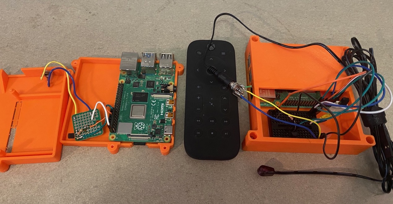
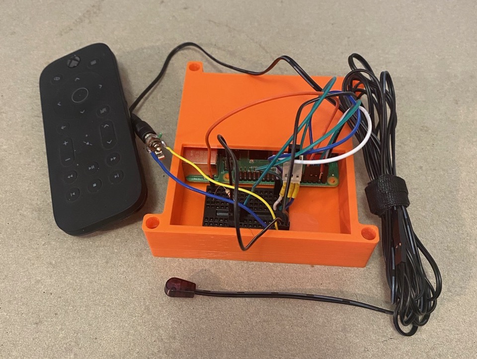
The hardware required for receiving IR input is reasonably simple. The recommendation is to prototype the circuit and then permanently solder it when everything has been tested.
In addition to the Raspberry Pi, a TSOP38238 infra red receiver, prototyping bread board and jumper wires are needed.
TSOP38238 Infra Red receiver:
https://www.creatroninc.com/product/tsop38238-infrared-receiver-38khz/
https://www.sparkfun.com/products/10266
https://www.adafruit.com/product/157
Breadboard:
https://www.creatroninc.com/product/mini-breadboard-white/
https://www.sparkfun.com/products/12043
https://www.adafruit.com/product/65
Jumper wires:
https://www.creatroninc.com/product/6-m-f-jumper-wire-10-pack/
https://www.sparkfun.com/products/9140
https://www.adafruit.com/product/826
The wiring diagram is as follows:
A) White wire, Pin 1, +3V3, output power
B) Green wire, Pin 6, GND, ground
C) Blue wire, Pin 8, GPIO 14, input signal
              Pin 1 Pin2
           +3V3 [A] [ ] +5V
 SDA1 / GPIO  2 [ ] [ ] +5V
 SCL1 / GPIO  3 [ ] [B] GND
        GPIO  4 [ ] [C] GPIO 14 / TXD0
            GND [ ] [ ] GPIO 15 / RXD0
        GPIO 17 [ ] [ ] GPIO 18
        GPIO 27 [ ] [ ] GND
        GPIO 22 [ ] [ ] GPIO 23
           +3V3 [ ] [ ] GPIO 24
 MOSI / GPIO 10 [ ] [ ] GND
 MISO / GPIO  9 [ ] [ ] GPIO 25
 SCLK / GPIO 11 [ ] [ ] GPIO  8 / CE0#
            GND [ ] [ ] GPIO  7 / CE1#
             Pin 25 Pin 26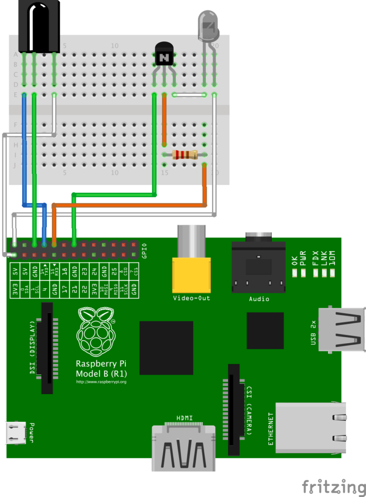
The image above includes the transmitter wiring which can be disregarded, IR transmission will be covered in a later post.
Setup the sensor on the breadboard. There are three leads, if you are using the TSOP38238, lens (‘bump’ on sensor) facing up and should be connected as follows:
+-----------------------+ A
|                       +-----------o +3.3V, Pin 1
|                       |
|      ______________   |
|     /                 |
|    (                  | B
|     \______________ + +-----------o GND, Pin 6
|                       |
|                       | C
|                     - +-----------o GPIO 14, Pin 8
+-----------------------+
For ControlKit IR hardware notes, please see:
Raspbian GPIO IR Hardware
Raspbian GPIO IR Hardware image
Configure Raspbian
Once the circuit is setup and connected to the Raspberry Pi, Raspbian needs to be configured to use the circuit.
The following is taken from ControlKit Raspbian Setup and Configure IR:
Raspbian Setup and Configure IR
Customize config.txt
As part of this configuration, IR transmission is also configured. If transmission is not needed, exclude dtoverlay=gpio-ir-tx,gpio_pin=15. Some of the output might be different as a result.
Update the config.txt variables:
sudo vi /boot/config.txtAdd the following to the end:
# BEGIN ADDED
dtoverlay=gpio-ir,gpio_pin=14
dtoverlay=gpio-ir-tx,gpio_pin=15
# END ADDED
Reboot:
sudo rebootConfirm gpio modules are loaded:
lsmod | grep gpiogpio_ir_recv 16384 0
gpio_ir_tx 16384 0List the devices:
cat /proc/bus/input/devicesI: Bus=0019 Vendor=0001 Product=0001 Version=0100
N: Name="gpio_ir_recv"
P: Phys=gpio_ir_recv/input0
S: Sysfs=/devices/platform/ir-receiver@e/rc/rc0/input0
U: Uniq=
H: Handlers=kbd event0
B: PROP=0
B: EV=100013
B: KEY=fff 0 0 4200 108fc32e 2376051 0 0 0 7 158000 4192 4001 8e9680 0 0 10000000
B: MSC=10A Note About rc0 and rc1
Normally the IR receiver is assigned to /sys/class/rc/rc0. However, due to the nature of multi threaded device probe, the receiver device can be assigned to /sys/class/rc/rc1.
In the following notes, when ir-keytable is called with -s rc0 and there is no response or an error, use -s r1.
If no -s is specified, rc0 is default. However due to the possibility of the receiver being assigned to rc1 during boot, it is recommended to always specify -s. In this way if the ‘wrong’ device is used and error will appear.
Install ir-keytable
To install ir-keytable, run:
sudo apt-get install ir-keytable -yTo confirm install, run:
ir-keytableFound /sys/class/rc/rc0/ (/dev/input/event0) with:
Name: gpio_ir_recv
Driver: gpio_ir_recv, table: rc-rc6-mce
LIRC device: /dev/lirc1
Attached BPF protocols: Operation not permitted
Supported kernel protocols: lirc rc-5 rc-5-sz jvc sony nec sanyo mce_kbd rc-6 sharp xmp imon
Enabled kernel protocols: lirc rc-6
bus: 25, vendor/product: 0001:0001, version: 0x0100
Repeat delay = 500 ms, repeat period = 125 msTest Remote with ir-keytable
Test the remote to see if it is using an existing ir kernel protocol. Enable all the kernel protocols:
sudo ir-keytable -p allProtocols changed to lirc rc-5 rc-5-sz jvc sony nec sanyo mce_kbd rc-6 sharp xmp imon Confirm the IR receiver device is working, run:
sudo ir-keytableFound /sys/class/rc/rc0/ (/dev/input/event0) with:
Name: gpio_ir_recv
Driver: gpio_ir_recv, table: rc-rc6-mce
LIRC device: /dev/lirc1
Attached BPF protocols: Operation not supported
Supported kernel protocols: lirc rc-5 rc-5-sz jvc sony nec sanyo mce_kbd rc-6 sharp xmp imon
Enabled kernel protocols: lirc rc-5 rc-5-sz jvc sony nec sanyo mce_kbd rc-6 sharp xmp imon
bus: 25, vendor/product: 0001:0001, version: 0x0100
Repeat delay = 500 ms, repeat period = 125 msThe /sys/class/rc/rc0/ indicates that the rc0 device is being used.
Test remote with rc0:
ir-keytable -t -s rc0Point remote at the receiver and press buttons, confirm responses to button presses:
Testing events. Please, press CTRL-C to abort.
756.890042: lirc protocol(rc6_mce): scancode = 0x800f0416 toggle=1
756.890091: event type EV_MSC(0x04): scancode = 0x800f0416
756.890091: event type EV_KEY(0x01) key_down: KEY_PLAY(0x00cf)
756.890091: event type EV_SYN(0x00).
757.080039: event type EV_KEY(0x01) key_up: KEY_PLAY(0x00cf)
757.080039: event type EV_SYN(0x00).
757.110056: lirc protocol(rc6_mce): scancode = 0x800f0416
757.110092: event type EV_MSC(0x04): scancode = 0x800f0416
757.110092: event type EV_KEY(0x01) key_down: KEY_PLAY(0x00cf)
757.110092: event type EV_SYN(0x00).
757.300037: event type EV_KEY(0x01) key_up: KEY_PLAY(0x00cf)
757.300037: event type EV_SYN(0x00).
757.310052: lirc protocol(rc6_mce): scancode = 0x800f0416 toggle=1
757.310082: event type EV_MSC(0x04): scancode = 0x800f0416
757.310082: event type EV_KEY(0x01) key_down: KEY_PLAY(0x00cf)
757.310082: event type EV_SYN(0x00).
757.500038: event type EV_KEY(0x01) key_up: KEY_PLAY(0x00cf)
757.500038: event type EV_SYN(0x00).
The rc6_mce indicates that the remote is using the rc6_mce protocol.
If the protocol is not identified, the remote is not using a recognized kernel protocol and additional configuration is needed. The unsupported remote configuration is out of scope of this post.
2020-02-13-raspbian-buster udev Bug
There is a bug in the udev rules for 2020-02-13-raspbian-buster that will prevent the rc_keymaps from being loaded at start.
To fix, edit:
sudo vi /lib/udev/rules.d/60-ir-keytable.rulesMake the following change, comment out the last line and replace:
# CHANGED
#ACTION=="add", SUBSYSTEM=="rc", RUN+="/usr/bin/ir-keytable -a /etc/rc_maps.cfg -s $name"
ACTION=="add", SUBSYSTEM=="input", SUBSYSTEMS=="rc", KERNEL=="event*", ENV{.rc_sysdev}="$id", RUN+="/usr/bin/ir-keytable -a /etc/rc_maps.cfg -s $env{.rc_sysdev}"
Configure ir-keytable for Kernel Protocol
This assumes that the remote being used supports the rc-6 protocol.
Copy the configuration from /lib/udev/rc_keymaps for the remote to /etc/rc_keymaps:
sudo cp /lib/udev/rc_keymaps/rc6_mce.toml /etc/rc_keymapsReboot:
sudo rebootTest with:
ir-keytable -t -s rc0Point remote at the receiver and press buttons, confirm responses to button presses:
Testing events. Please, press CTRL-C to abort.
1001.030050: lirc protocol(rc6_mce): scancode = 0x800f0416
1001.030096: event type EV_MSC(0x04): scancode = 0x800f0416
1001.030096: event type EV_KEY(0x01) key_down: KEY_PLAY(0x00cf)
1001.030096: event type EV_SYN(0x00).
1001.220039: event type EV_KEY(0x01) key_up: KEY_PLAY(0x00cf)
1001.220039: event type EV_SYN(0x00).
1001.270088: lirc protocol(rc6_mce): scancode = 0x800f0416 toggle=1
1001.270120: event type EV_MSC(0x04): scancode = 0x800f0416
1001.270120: event type EV_KEY(0x01) key_down: KEY_PLAY(0x00cf)
1001.270120: event type EV_SYN(0x00).
1001.460032: event type EV_KEY(0x01) key_up: KEY_PLAY(0x00cf)
1001.460032: event type EV_SYN(0x00).
Shutdown Raspbian via Remote
The following will setup a mapping from the button press KEY_SLEEP to remote-poweroff.sh script.
remote-poweroff.sh Script
The content of the script could be anything, in this example the Raspberry Pi will be rebooted.
Create a folder to store the scripts in /opt/scripts and create a file called remote-poweroff.sh:
sudo mkdir /opt/scripts
sudo vi /opt/scripts/remote-poweroff.sh
#!/bin/bash
sudo /sbin/shutdown nowChange ownership and make executable:
sudo chown pi.pi /opt/scripts/remote-poweroff.sh
sudo chmod u+x /opt/scripts/remote-poweroff.sh
sudo chmod +x /opt/scripts/remote-poweroff.sh
Add the user nobody to the list of users who can reboot without a password:
sudo visudo# ADDED
nobody ALL =NOPASSWD: /sbin/shutdown*Test script, running this should restart the Raspberry Pi:
/opt/scripts/remote-poweroff.shFor ControlKit notes, please see:
Raspbian Scripts Reboot
Headless or No Desktop Keybindings
Use this approach if the system is headless, has no monitor and not using a desktop. However, it will also work with the Desktop (or non lite) version.
The triggerhappy service is used, it can map events to scripts and is installed by default on Raspbian.
To view the input that the tiggerhappy is receiving, start triggerhappy in dump mode:
thd --dump /dev/input/event*Press a key or button on the remote to confirm it is being received. In this example the KEY_SLEEP is pressed. The output should look like:
EV_KEY    KEY_SLEEP   1   /dev/input/event0
# KEY_SLEEP    1   command
EV_KEY    KEY_SLEEP   0   /dev/input/event0
# KEY_SLEEP    0   command
EV_KEY    KEY_SLEEP   1   /dev/input/event0
# KEY_SLEEP    1   command
EV_KEY    KEY_SLEEP   0   /dev/input/event0
# KEY_SLEEP    0   command
Type control-c to exit.
Now create a new configuration file:
sudo vi /etc/triggerhappy/triggers.d/remote-poweroff.confPaste in the configuration:
KEY_SLEEP 1 /opt/scripts/remote-poweroff.shRestart triggerhappy to load changes:
sudo systemctl restart triggerhappyTest by pressing the configured key or button, this should call remote-poweroff.sh and start a shutdown.
For ControlKit Keycode Events and Keybindings notes, please see:
Keycode Events and Keybindings
Summary
There are several moving, parts, but once the hardware is created and the basics are installed, there is quite a lot of flexibility.
References
The following are references that I found helpful:
https://www.mess.org/2019/03/04/How-to-add-support-for-a-new-remote-control/
https://www.mess.org/2020/01/26/Moving-from-lirc-tools-to-rc-core-tooling/
https://www.sigmdel.ca/michel/ha/opi/ir_03_en.html